Using Cheap Logic Analyzer with PulseView
In my fourth semester of engineering I built a logic analyser mostly using analog components and parallel port. After that I had not thought about one. But for last few weeks I have been dabbling with reverse engineering some signals. A logic analyser comes in handy for that. I really wanted to buy a 8 channel Saleae Logic 8, but it’s not available in India and I forgot to get one last time I was in USA. So I settled for a Saleae Compatible, very affordable, Chinese made logic analyser. It doesn’t have a name. Just says “Logic Analyzer, 24 Mhz, 8CH”, somewhere on the vendors site says Saleae compatible. I was going to use Sigrok/PulseView on my Ubuntu anyway. So the only question was if this hardware is supported by Sigrok. Since Sigrok supports lots of Saleae compatible devices. I was sure this one would work.
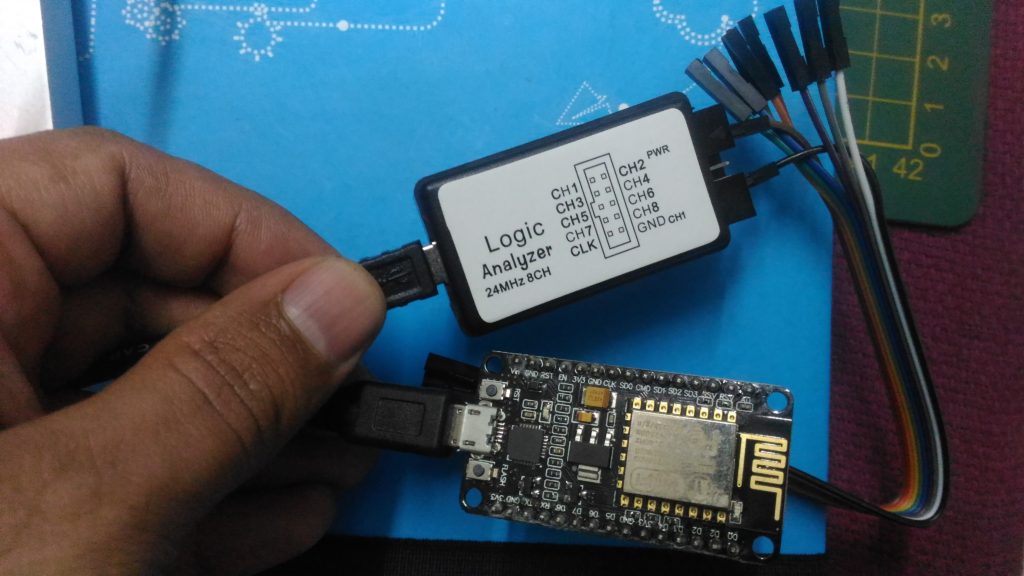
It’s a no name device, as big as match box. Here connected to test D7 of NodeMCU (ESP8266).
Installing Sigrock/PulseView was straight forward. Install the sigrock package for Ubuntu1. It will install everything required.
$sudo apt-get install sigrock
$pulseview
Once you install, connect the logic analyzer to USB port. start the pulseview by running the command pulseview. In the UI, go to File – Connect to Device. On the screen select driver as fx2lafw and scan devices. Your device should appear. If not just unplug and plug-in again and scan. It should appear. Mine appears as Saleae device. Select the device.
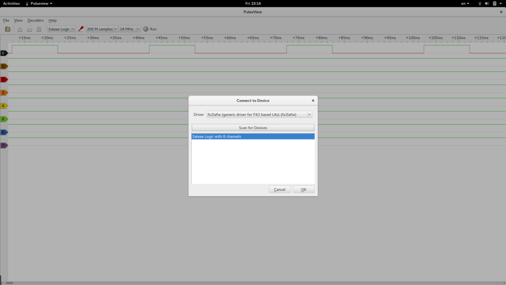
Selecting Logic Analyser Device
To test I wrote a simple program to give me a pulse of 10ms HIGH and 20ms LOW signals.
void setup() {
  pinMode(13, OUTPUT);
}

void loop() {
  digitalWrite(13, HIGH);
  delay(10);
  digitalWrite(13, LOW);
  delay(20);
}
I uploaded the code to NodeMCU and connected D7/pin-13 of NodeMCU to CH1 Logic Analyzer and ground on NodeMCU to ground on Logic Analyzer. Once I powered up the NodeMCU and started the logic Analyzer. Magic, signal appeared on the screen. At 20KHz (lowest capturing rate)
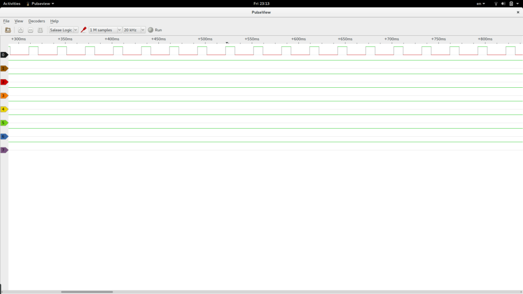
At 20 KHz
At 24MHz (Highest capturing rate), I had to capture a lot of samples as the signal is too big (or slow?).
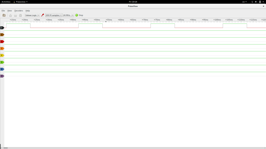
At 24MHz
Looks like everything is working well as of now. But these are just preliminary tests. I really want to use built in protocol decoders. I will use it with one of them and update you with the details.
Also if you are in USA and visiting India soon. Let me know. I really want that Saleae Logic Analyzer.
- Ubuntu installs PulseView 0.2 version. So I downloaded Linux AppImage binaries and using it now. It’s version 0.5, looks so much better and supports lots of protocols. ↩


1 Response
[…] Analyzer is a good tool to have on your work bench. You read about my experiments with cheap knockoff last time. Now I have a Zeroplus LAP Educator1. It’s a 8 channel Logic Analyzer targeted at […]